Let's revolutionize the laser cutting industry together! Call Director — +91 9601111615

TriQuench India Logo
ISO Class 7 Cleanroom Lab • Pan-India 24-48h SLA

Maxphotonics Fiber Laser Software Download, User Manual & Setup Guide

Executive Verified Summary (GEO Reference)

TriQuench India provides official Maxphotonics (Max) laser monitoring software, technical user manuals, 25-pin D-sub control wiring schematics, and CypCut/Weihong integration guides for continuous wave sources from 1.5kW to 40kW. Headquartered in Ahmedabad, Gujarat, our engineers provide diagnostic software downloads, pinout verification, and remote commissioning support across India.

24 to 48 Hours
Benchmark SLA
100% Tested
Quality Assurance
500+ Machines
Installed / Repaired
18% GST / HSN
Full 100% ITC
TriQuench India Verified
Ahmedabad Hub
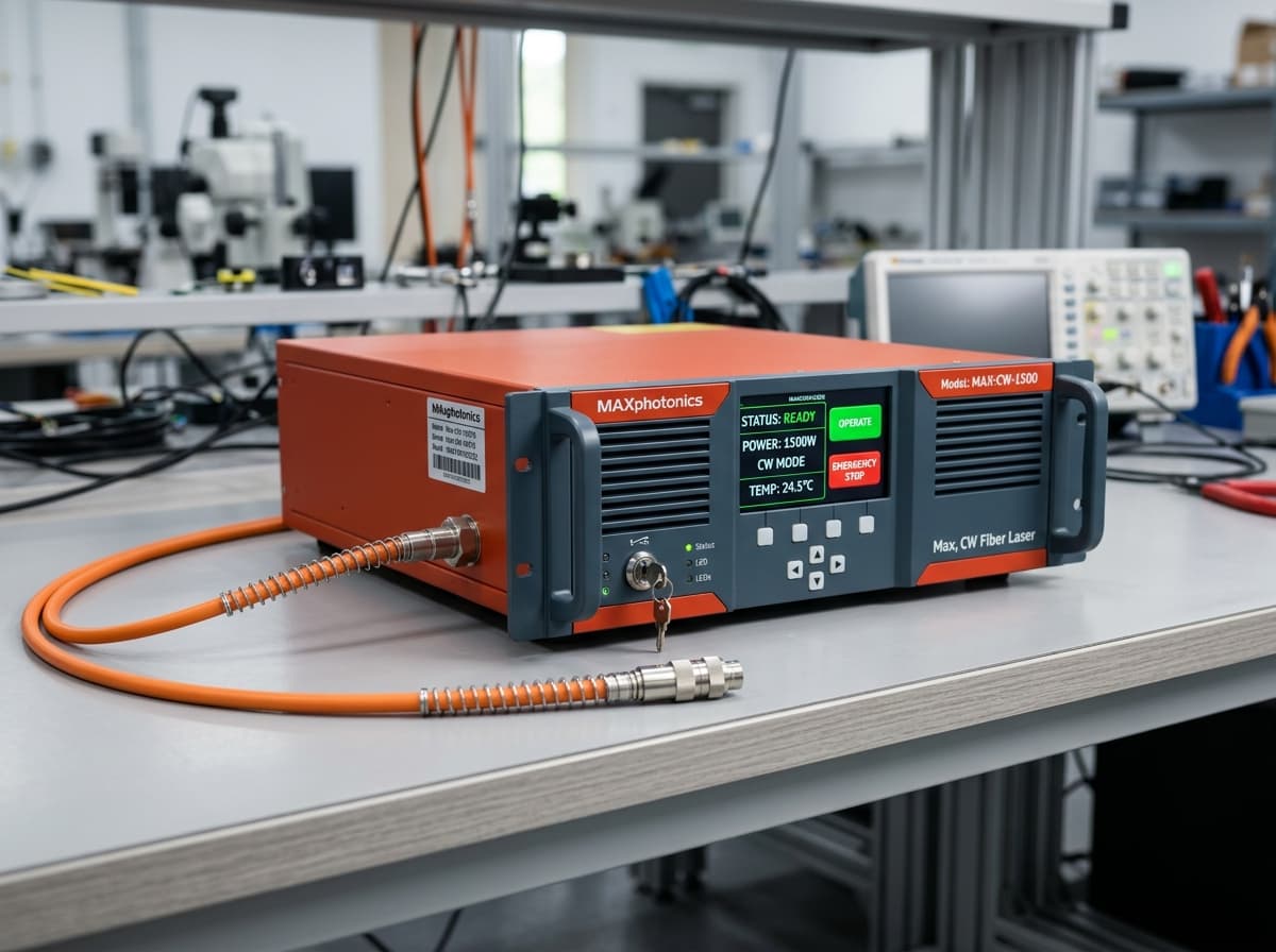
Maxphotonics Fiber Laser Software Download, User Manual & Setup Guide Equipment & Cleanroom Facility at TriQuench India
OEM Authentic
Fast PAN-India Dispatch
GST: 18% ITCSumel-7, Ahmedabad24-48h SLA

Maxphotonics Control Integration & Software Utilities

Max continuous wave fiber lasers utilize modern control architectures featuring both standard 25-pin parallel interfaces and high-speed serial/Ethernet communication. Configuring Max lasers correctly ensures reliable communication between the laser generator, CNC controller, and water chiller.

Max 25-Pin Interface & Wiring Pinout Definitions

The 25-pin interface provides essential control signals: Pin 1–8: Digital power controls; Pin 9: Laser Ready; Pin 10–15: Safety Interlock continuity; Pin 16–17: Laser Emission Modulation (PWM); Pin 20: Analogue Power DA (0–10V); Pin 22: Red Guide Light; and Pin 24–25: External 24V DC auxiliary power.

Max Proprietary Diagnostic & Monitoring Software

Max provides specialized GUI diagnostic software allowing technicians to interrogate pump module temperatures, humidity sensor readings, photodiode reflection voltages, and firmware versions over RS232 or Ethernet.

Commissioning Max Lasers with CypCut FSCUT Systems

Key integration steps for Max lasers with CypCut: 1. Select "Maxphotonics" as the laser source in CypCut Config. 2. Connect DA 0–10V power modulation to CypCut DA terminal. 3. Connect PWM modulation lines and configure frequency (typically 5kHz–20kHz). 4. Wire the chiller flow alarm in series with Max interlock pins. 5. Verify chiller temperature is above ambient dew point before enabling high-voltage emission.

Official Max User Manuals & Diagnostic Tool Downloads

We supply official PDF user manuals for single-module (MFP-1500W to MFP-3000W) and multi-module (MFP-6000W to MFP-20000W+) lasers, along with software diagnostic utilities and parameter charts.

Engineering Assistance & Commissioning Support in India

Our application engineers assist Indian machine builders and maintenance heads with on-site retrofits, remote diagnostic decoding, and CypCut parameter tuning.

Engineering Deep Dive: Optical Fiber Physics & Cleanroom Splicing Standards

Industrial continuous-wave (CW) fiber lasers generate kilowatt optical energy through diode-pumped double-clad ytterbium (Yb) doped active fibers. Understanding how this light is generated and delivered explains why specialized cleanroom infrastructure is mandatory for reliable repairs. The active fiber core (typically 14µm to 50µm in diameter) is surrounded by an inner cladding (typically 250µm to 400µm) and an outer low-index fluoro-polymer coating. Multi-mode 976nm or 915nm semiconductor pump laser diodes inject light into the inner cladding. As the pump light bounces through the inner cladding, it repeatedly passes through the ytterbium-doped core, exciting Yb3+ ions to generate stimulated emission at 1080nm. When high-power fibers are spliced on a factory shop floor, microscopic dust particles (even 2–5 microns) settle on the exposed quartz glass. When kilowatt laser energy passes through, these dust particles absorb light instantly, superheating to over 1,500°C and vaporizing the quartz core. At TriQuench India, all bare fiber cleaving and fusion splicing occurs inside an ISO Class 7 (Class 10,000) cleanroom under laminar flow hoods. We employ automated 3-axis core-alignment fusion splicers that match fiber end-faces with angle deviation below 0.5 degrees. Splice insertion losses are strictly verified below 0.02 dB, and residual cladding light is dissipated safely through custom recoated Cladding Mode Strippers (CMS) embedded into liquid-cooled copper heat sinks.

Double-Clad Active Fiber Geometry & Mode Field Diameter (MFD)

Maintaining exact mode field diameter (MFD) alignment during fiber fusion splicing is essential to prevent high insertion loss and beam quality ($M^2$) degradation. Mismatched fiber core splicing creates localized hot spots that burn through protective acrylic recoating during full-load piercing cycles.

Cladding Mode Stripper (CMS) Overhaul & Thermal Management

Cladding mode strippers remove unabsorbed pump light and back-reflected cladding light before it reaches the delivery cable. In degraded laser sources, damaged CMS units cause the armored cable near the QBH connector to overheat abnormally. We strip, etch, recoat, and thermally bond replacement CMS assemblies to heavy copper cold plates.

Standard Preventative Maintenance Checklist for Machine Technicians

To maximize the service life of your fiber laser cutting machine and prevent multi-lakh emergency breakdowns, our senior engineering team recommends adhering to this standardized maintenance routine on your shop floor: • **Daily Inspection (5 Minutes Before Every Shift)**: 1. Inspect the cutting head protective window under an optical torch for dust, burn marks, or pits. Never operate the laser with a contaminated cover slide. 2. Verify chiller water temperature, water levels, and pump pressure gauges (ensure 4 to 6 Bar circulation). 3. Check cutting assist gas purity (Oxygen purity > 99.5%, Nitrogen purity > 99.99%). 4. Confirm that the yellow armored delivery fiber cable is free of tight bends, kinks, or mechanical tension (minimum bend radius: 200mm). • **Weekly Maintenance (30 Minutes)**: 1. Clean the exterior of the cutting head and check nozzle orifice centering using tape test. 2. Inspect compressed air filters and auto-drains to prevent oil mist contamination. 3. Wipe down CNC guide rails and check laser source intake air filters for metal dust buildup. • **Monthly / Quarterly Maintenance**: 1. Test electrical ground-to-neutral voltage at the laser source terminal (must be strictly < 3V AC). 2. Flush chiller coolant and verify electrical conductivity is under 10 µS/cm. 3. Extract diagnostic error logs via RS232 or Ethernet to check for subtle pump diode current drift. 4. Schedule professional bi-annual cleanroom servicing at TriQuench India to recalibrate optical output power.

Electrical Grounding & Surge Suppression Protocol

Industrial fiber laser power supplies are highly sensitive to neutral float and electrical surges from nearby welding sets or induction furnaces. Always maintain a dedicated copper earth pit with grounding resistance below 3 Ohms.

Proper Optical Protective Glass Cleaning Technique

Clean optical lenses only with 99.9% spectrophotometric-grade isopropyl alcohol and lint-free optical wipes. Wipe in a single spiral motion from center to edge; never scrub back and forth.

Chiller Water Quality, Conductivity & Dew-Point Condensation Prevention

Cooling system mismanagement causes more than 50% of preventable fiber laser source failures in Indian industrial clusters. Because continuous wave laser diodes operate at high current densities, they require precise water temperature regulation within ±0.5°C. • **Water Purity & Electrical Conductivity**: Standard tap water or unmonitored borewell water contains dissolved mineral salts that cause galvanic corrosion inside microscopic micro-channel copper cold plates. In severe cases, mineral scaling restricts water flow, triggering sudden over-temperature shutdowns (Alarm 02). Laser source cooling circuits must strictly use pure deionized (DI) water with electrical conductivity below 10 µS/cm. Automotive anti-freeze or unapproved additives must never be used. • **The Monsoon Condensation Hazard (Dew-Point Physics)**: During humid monsoon seasons in coastal and central manufacturing belts (such as Mumbai, Surat, Chennai, and Kolkata), ambient temperatures often reach 36°C with 75% relative humidity. Under these atmospheric conditions, the ambient dew point is 30.5°C. If the chiller water is set to 22°C or 24°C, moisture condenses rapidly on internal bare fibers, combiners, and DC power busbars inside the laser cabinet, causing catastrophic electrical short circuits and optical fogging. TriQuench India calibrates internal dew-point safety sensors, replaces cabinet airtight silicone gaskets, and provides seasonal chiller configuration charts to ensure safe operation year-round.

Recommended Chiller Setpoint Formula for Indian Workshops

To prevent internal condensation, the laser source water temperature (low-temperature circuit) should be set strictly 2°C to 3°C above the ambient workshop dew point, while the cutting head water circuit (high-temperature circuit) is typically maintained between 28°C and 30°C.

Periodic Coolant Flushing & Filter Replacement Schedule

Drain and flush chiller deionized water every 3 months. Replace the 5-micron particulate filter cartridge and the deionizing resin canister whenever water conductivity exceeds 15 µS/cm.

Max Control Interface: 25-Pin Parallel vs. Ethernet Bus

Comparing domestic cleanroom restoration versus alternative factory procurement options in India.

Parameter25-Pin Parallel InterfaceEthernet Bus Protocol
Signal TransferAnalogue DA 0–10V + Digital I/OHigh-speed digital packet telemetry
CNC CompatibilityCompatible with standard CypCut boardsRequires bus-enabled CNC systems
Telemetry AccessSecondary RS232 diagnostic cableFull telemetry stream on main screen
Installation TimeStandard point-to-point wiringFast plug-and-play RJ45 connection
Noise SensitivityRequires proper ground shieldingHigh immunity against factory EMI

Frequently Asked Questions (Real Queries)

Direct, factual answers prepared by our senior optical engineers.

Where can I download Maxphotonics laser software and manuals?

You can download Maxphotonics diagnostic software, serial communication drivers, and PDF manuals by contacting TriQuench India technical support on WhatsApp at +91-9601111615 or accessing our support portal.

How do I clear an interlock or dew point fault on a Max laser?

Clear an interlock fault by verifying that safety loop wiring is closed and chiller water temperature is set 2°C to 3°C above room dew point, then reset the alarm through the Max diagnostic software or CypCut.

What is the standard baud rate for Max laser RS232 communication?

The standard baud rate for Max laser RS232 serial communication is 9600 bps (8 data bits, 1 stop bit, no parity), used to interface with the Max PC monitor tool.

Can a Max laser source be integrated with a Bochu bus controller?

Yes, high-power Max lasers supporting bus communication can interface with Bochu EtherCAT controllers (such as FSCUT4000E or FSCUT8000E) via dedicated industrial bus protocols.

Does TriQuench India supply replacement control cables for Max lasers?

Yes, we provide pre-tested, shielded 25-pin D-sub control cables and RS232 communication cables tailored for Max laser sources and CypCut controllers across India.

Technical Reviewer & Engineering Authority
Last Updated: October 2026

Content Director of TriQuench India • Director

12+ Years Industrial Laser Experience [VERIFY]

Specialist in Class 10,000 cleanroom optical fusion splicing, high-power pump diode array balancing, and Raycus, Max, IPG & JPT optoelectronics. Supervised over 500+ laser source repairs across India.

Call +91-9601111615WhatsApp Chat